Inline Engine Crankshaft
Modeling a rotating assembly with real balance and manufacturing intent.
- Year
- 2024
- Software
- SolidWorks
- Focus
- Powertrain · Part Design · Rotating Machinery
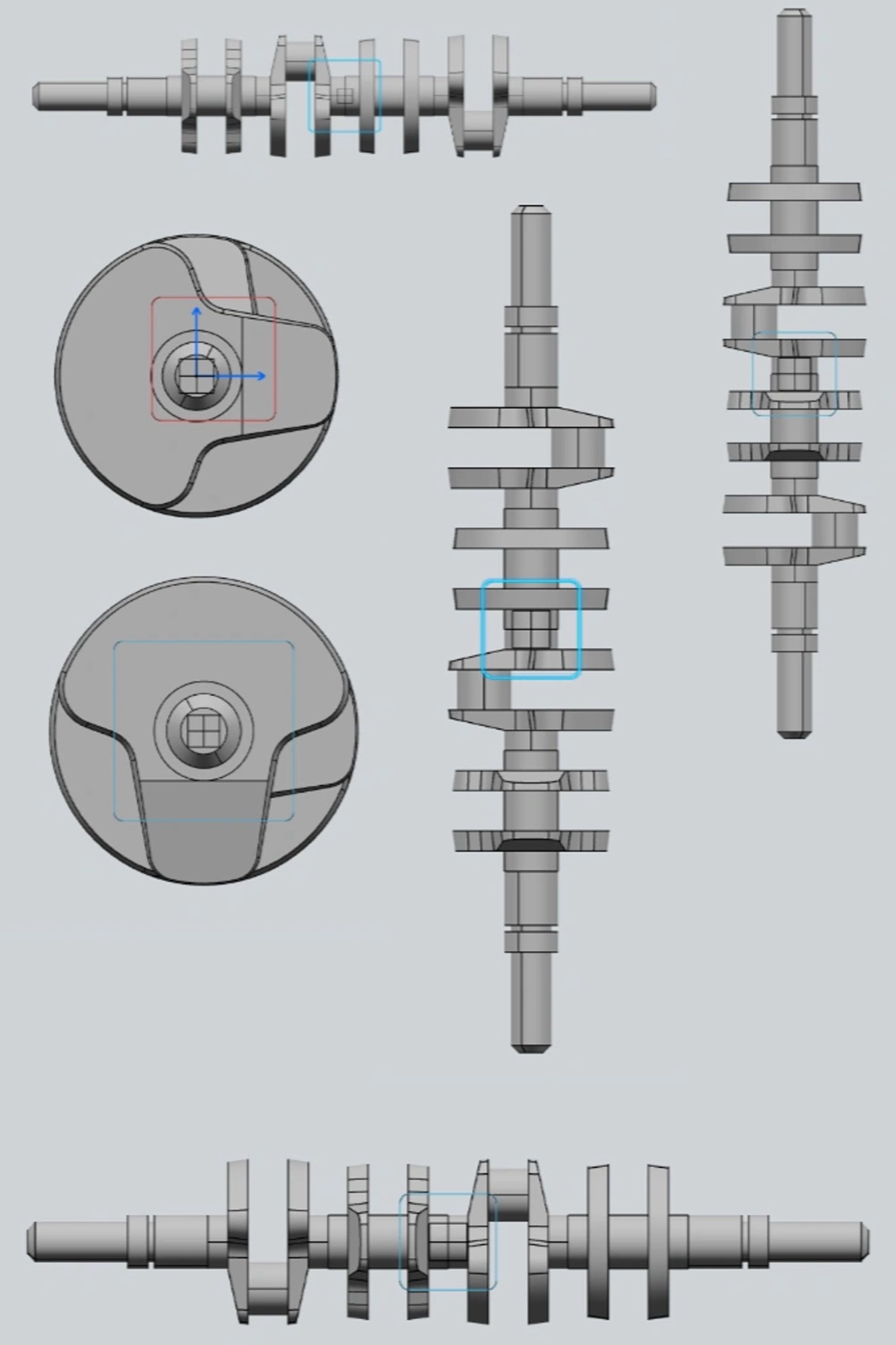
Overview
A crankshaft is one of the most demanding everyday mechanical parts: it converts linear combustion force into rotation while surviving enormous cyclic loads. I modeled one to understand how that function drives its shape.
The model captures the full sequence — main journals, crank pins phased around the axis, counterweights, and the fillets that keep stress concentrations in check.
The objective was a part that reads as genuinely manufacturable and balanced, not just a shape that looks like a crankshaft.
Engineering process
Decisions, iterations, and tradeoffs.
- 01
Phasing the throws
The crank pins are positioned around the rotational axis so the piston events are evenly spaced. Laying this out first fixed the fundamental geometry that everything else hangs from.
- 02
Counterweight balance
The counterweights are sized and placed to oppose the reciprocating and rotating masses. Reasoning about balance while modeling turned an abstract requirement into concrete geometry.
- 03
Fillets that matter
The radii where journals meet webs are structural, not cosmetic — they are exactly where fatigue cracks start. I treated them as a deliberate design feature rather than an afterthought.
Gallery
CAD · Surfacing · Renders
What I learned
On a rotating part, mass distribution is a design input from the first sketch, not a check at the end.
The unglamorous features — fillets, journal transitions — are often the ones doing the structural work.
I would follow this up with a simple FEA pass to see whether my intuition about the fillet stresses holds.
Next project