Flanged Bayonet Coupling
A quick-connect hub where the interface is the whole design.
- Year
- 2024
- Software
- SolidWorks
- Focus
- Part Design · Mechanical Interfaces · Machining
Overview
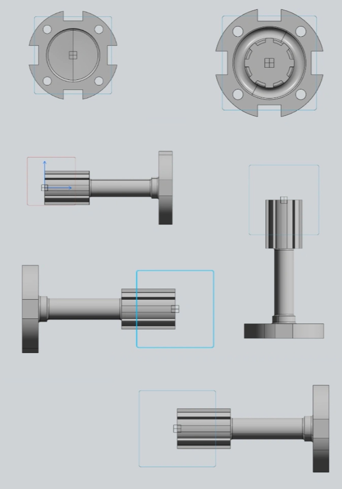
A coupling exists only to connect two things reliably, so every feature here serves an interface: a splined boss to transmit torque, a bolt-hole flange to mount it, and bayonet slots for a quick-release lock.
I designed it to think explicitly about how parts meet — clearances, pilot diameters, and the sequence a technician would follow to install and remove it.
The result is a part whose form is almost entirely dictated by the components it has to talk to.
Engineering process
Decisions, iterations, and tradeoffs.
- 01
Interfaces first
I started from the mating features — the spline, the bolt circle, the bayonet lands — and let the connecting geometry follow. When the interfaces are right, the body between them is straightforward.
- 02
Designing for assembly
The bayonet slots are shaped for a twist-to-lock motion, and the flange bolt pattern is spaced for tool access. I was designing the installation, not just the object.
- 03
Concentric integrity
Boss, bore, and flange share one axis so the coupling seats square. Keeping them coaxial through every edit protected the fit that the whole part depends on.
Gallery
CAD · Surfacing · Renders
What I learned
For connecting parts, the interfaces are the design — model them first and the rest resolves itself.
Thinking through the assembly sequence surfaces clearance problems the CAD model alone won't show.
I would add proper tolerances and a mating part next, to prove the fit rather than assume it.
Next project